Electronic Design
Group project:
Group Assignment
Decided to go with digital multimeter since its readily available for me as an individual
some of the tests decided to do is are as follows
Continuity of copper traces
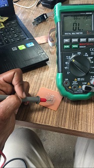
short circuit test
open tests
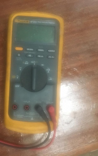
all the above were done using the digital multimeter
I decided to go with the ATtinyISP programmer which looks like the following
.png)
but the i decided to add a bit of challange to myself and add arduino to it. In such a way it will be an intergration of the two
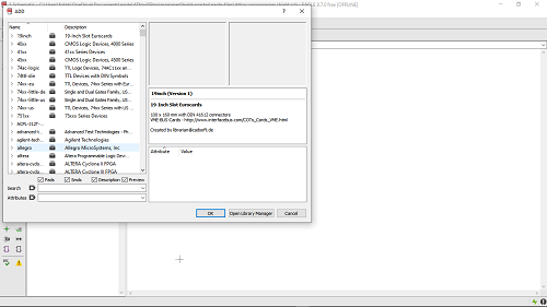
i decided to go with Eagle software
This is because i found it easy to interact with the components and everthing on its library
KIcad was another software that i interacted with, this was almost the same with eagle software. the only difference i noticed it was that adding libraries was a bit hard for me atleast.
First design
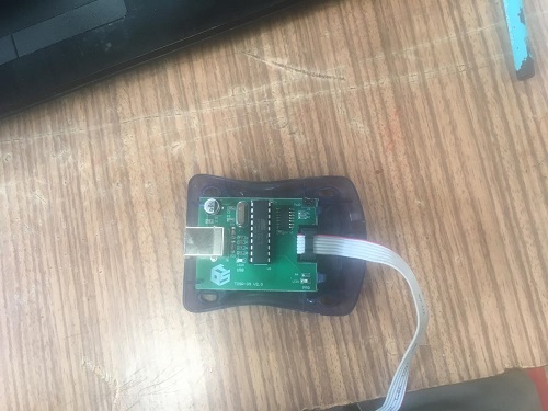
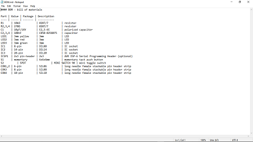
Before designing i had to interogate the board again and know which components as well know which trace goes where and here is a groupd of componts i was able to list by only observing
the list is as below:
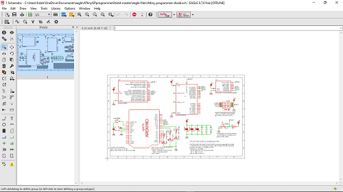
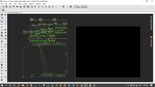
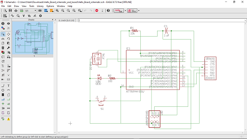
i started by creating am empty schematic and placing the components ub the working area and later saving as Attiny arduino shield
the i moved on to drawing the circuit of where each component connected to
And the final schematic looked like the following
I moved on to designing the board and decided it should look exactly or almost the same with the one i was using as reference at this point i realized that there was the same done project the same as i was thinking in line. the file is found at github here is thelink
i decided to use this as reference and continue designing since i was far gone
i continued to arrange the footprints of each components and as well draw the traces
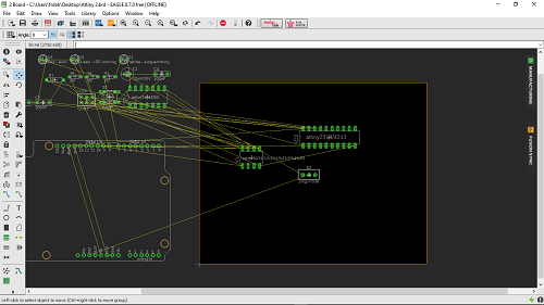
this is where i learned about auto routining which i was advised against
The final board looked like this
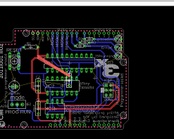
comparing the designed with the original
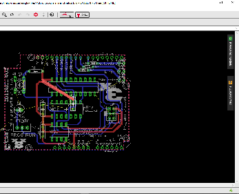
this gave me a deeper understanding of design rules of the pcb and it was a deeper tutorial to follow
you can get the files here of the original designed files
Design filesSecond design
After leraning on how to manuver on the eagle software i decided to go ahead and design what was required for the week which was:
redraw an echo hello-world board, add (at least) a button and LED (with current-limiting resistor)
First it was about finding components on eagle libraries and adding to sketch
Proceeded on making tracess on the on the schematic and labbling each components as well as noting which components are available for use
i proceed on to designing a pcb which is very easy(after larning tricks of eagle)
.png)

which was developed after learning this trick of SCH/BRD button
i continued to placing the footprinting and drawing the traces on working area
afterword i went ahead and removed the excessive labbling to make sure there would be no shorting
.png)
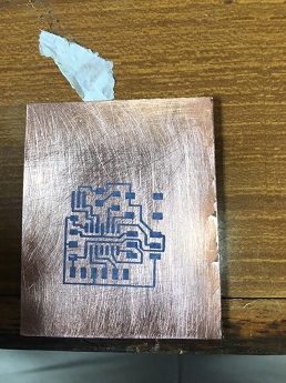
I saved this as pdf and printed it in a glossy paper which i used to traffer to pcb board
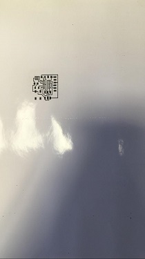
i ttransfered it using the iron box
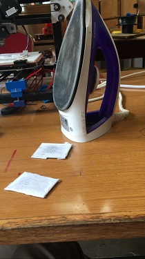
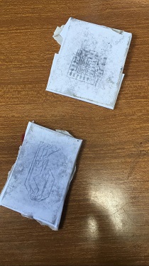
as you can see this is not the most effecient way as it may come out well or some traced may be left on the paper during transer
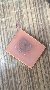
i continues to etch using the chemical i mixed during week 4
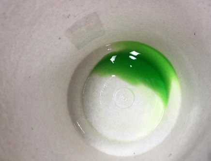
this was the final product which was much better then what i got in week 4
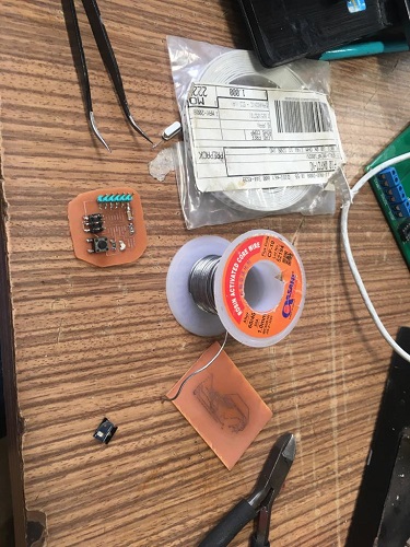
Electronic soldering
i went ahead and looked out for Electronic:
i went ahead and did soldering
you can get the files
Design filesThis work was proceeding from week four and still developing
Programing
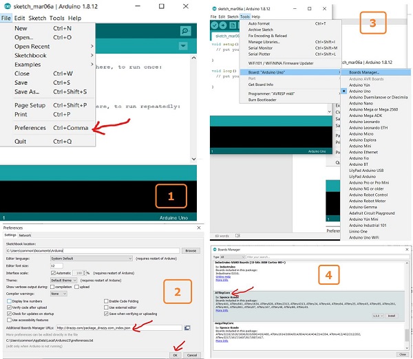
to program the board i used arduino IDE and make sure i did it correctly I used the following link
Since i had arduino IDE in my laptop i went ahead to following the tutorial:
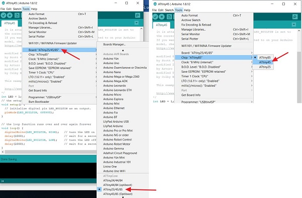
After setting arduino IDE it was time to test simple code like blinking an LED to the board i had designed. Here is how i went through it:
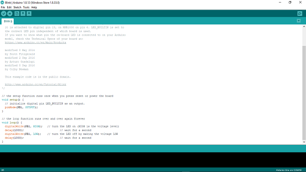 this was the outcome of my trial.
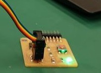
I found this way being easier for those who are starting in AVR programing since of there is interaction between with arduino IDE which has very basic and good and understanding of simple code
